Products & systems / Randek Truss System NT

ROOF TRUSS

Randek Truss System NT

Every type of roof truss, pressed the proven way.

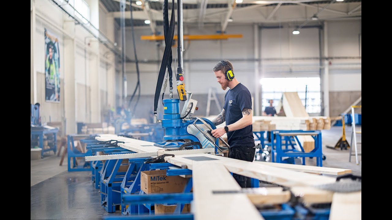
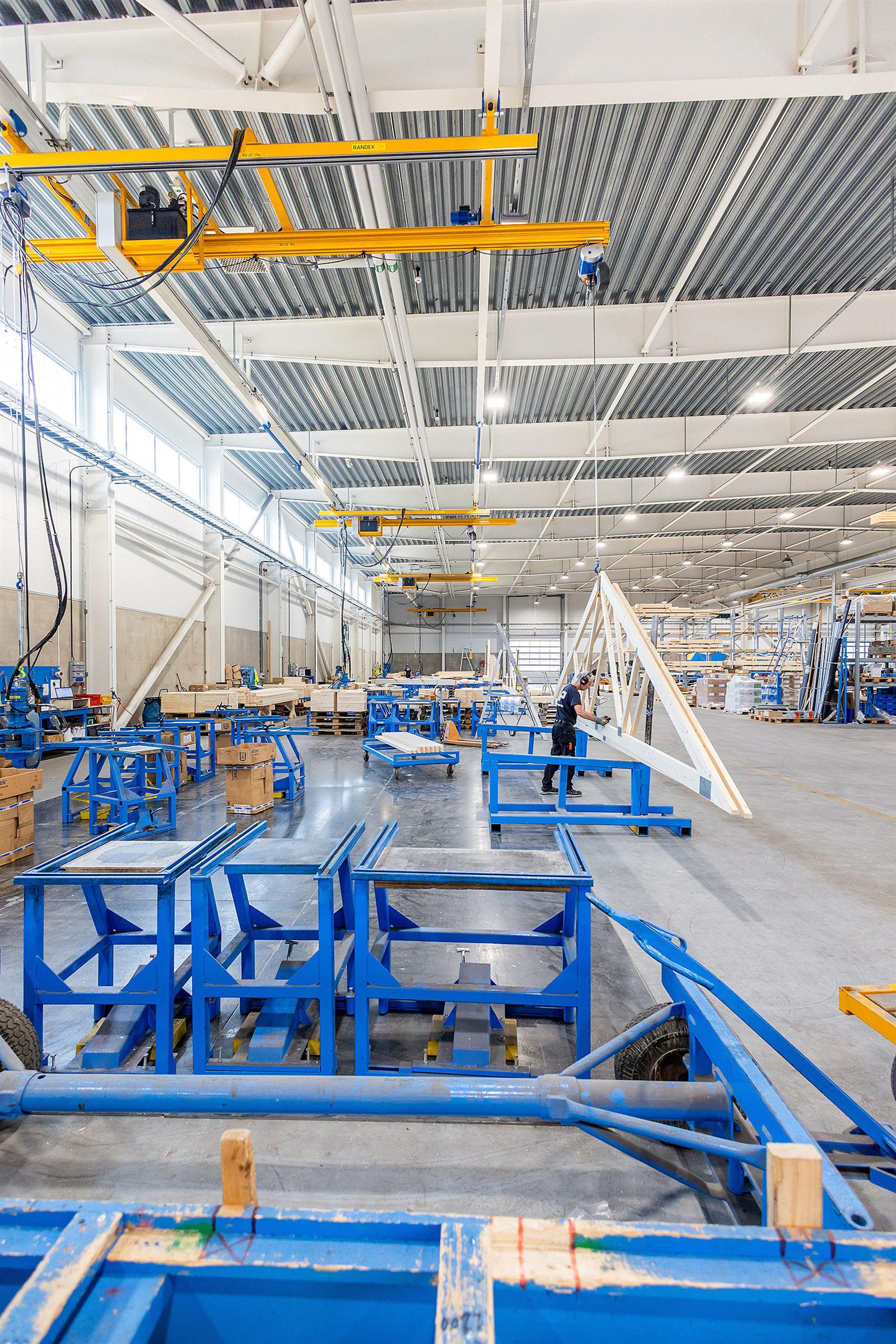
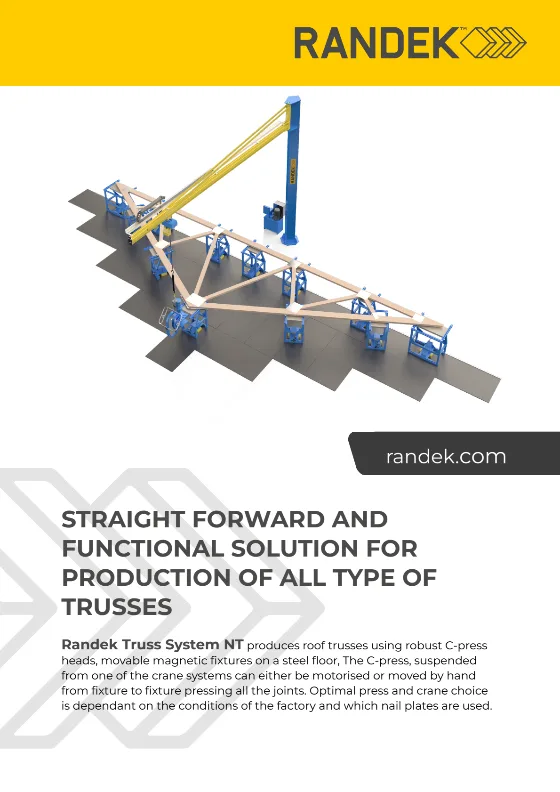
Truss System NT is Randek’s equipment for traditional and effective manufacturing of roof trusses: a straightforward, functional system that produces every type of truss, and the practical route into truss production for any builder working in wood. The truss frame is laid on movable fixtures that lock to a steel floor with permanent magnets, one at each joint. A C-press head, suspended from one of five crane systems, is moved from fixture to fixture by hand or by motor and presses every nail plate. LAP CAD-PRO laser projection, supplied by LAP GmbH, shows exactly where each member and nail plate goes. The right press and crane depend on your building and the nail plates you use, so we choose them with you.

Randek’s equipment for traditional roof-truss manufacturing: C-press heads from 23 to 50 tonnes (metric, 225–490 kN) on a crane, magnetic fixtures on a steel floor and LAP CAD-PRO laser projection.

  • Every truss type, one flexible system. Fixtures move freely on the steel floor, so the station resets from one truss geometry to the next without fixed jigs.
  • Magnetic fixtures that stay put. Permanent magnets lock each fixture to a 10 mm steel floor; a hydraulic jack and a foot pedal release it for the next setup.
  • Press heads from 23 to 50 tonnes (metric, 225–490 kN). Robust C-shaped hydraulic presses with two-handed control, matched to the nail plates you use. They are well suited to splicing timber too.
  • A crane for the building you have. Wall-mounted, column-mounted, overhead, light overhead or counter-balanced, moved by hand or motorised.
  • Press from both sides. An electric chain hoist lifts the press over the truss so joints can be pressed from the inside, and a gas spring compensates the press stroke.
  • Guided by laser. LAP CAD-PRO laser projection, supplied by LAP GmbH, shows exactly where each member and nail plate belongs, cutting setup and marking time.
TIMBER ROOF TRUSSES

Timber roof trusses, joined by nail plates

Truss System NT presses nail plates into timber roof-truss joints the traditional way: the truss frame held on permanent-magnet fixtures against a steel floor, with the C-press suspended from a crane and LAP CAD-PRO laser projection guiding the build-up.

COMPONENTS

What the system is built from

Component 1

C-press heads

Robust C-shaped hydraulic press heads, from 23 to 50 tonnes (metric, 225–490 kN), press the nail plates into each joint. The open C-shape reaches in from the edge of the truss, and a two-handed control keeps the operator’s hands clear during the press cycle.
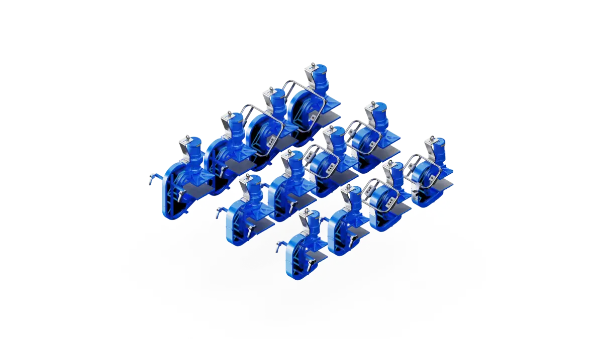
Randek C-press heads for Truss System NT in several sizes, isometric view
Component 2

Magnetic fixtures & steel floor

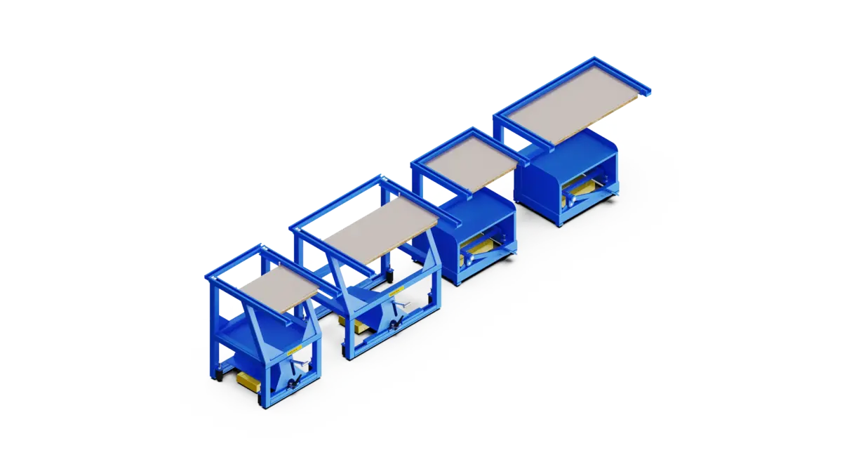
Fixtures with permanent magnets lock against a 10 mm levelled steel floor, one at each truss joint. Lift the magnet with the hydraulic jack and release it with the foot pedal, and the fixture slides easily to the next geometry. Supports and fasteners on top shape the timber before pressing.

Randek magnetic fixtures for the Truss System NT steel floor, isometric view
Component 3

Crane system

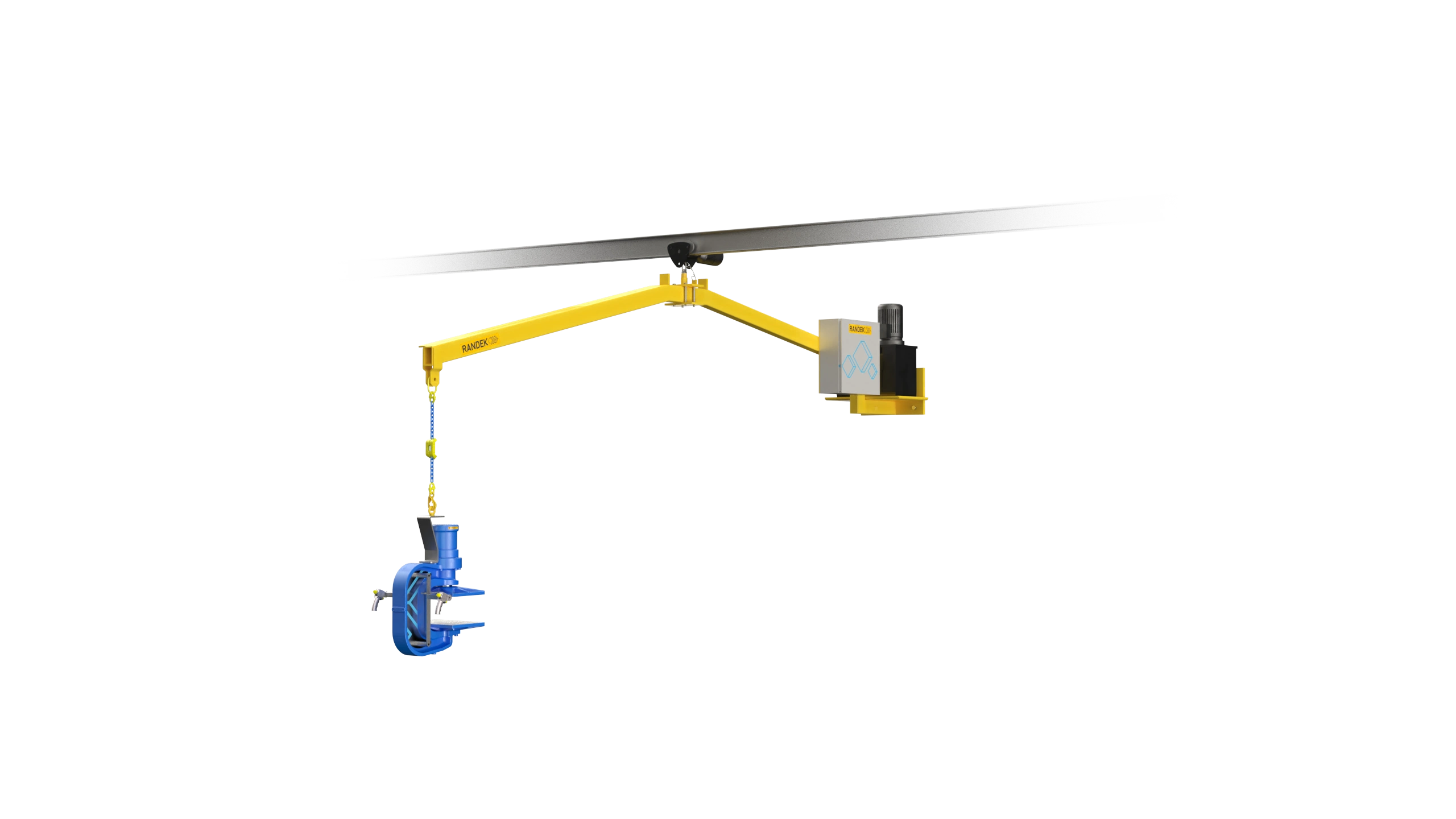
The crane carries the C-press over the truss so the operator reaches every joint without lifting it. An electric chain hoist sets the working height and lifts the press over the truss to press from the inside.

A Truss System NT press head hanging from a swing arm on an overhead crane, isometric view
Component 4

LAP CAD-PRO laser projection

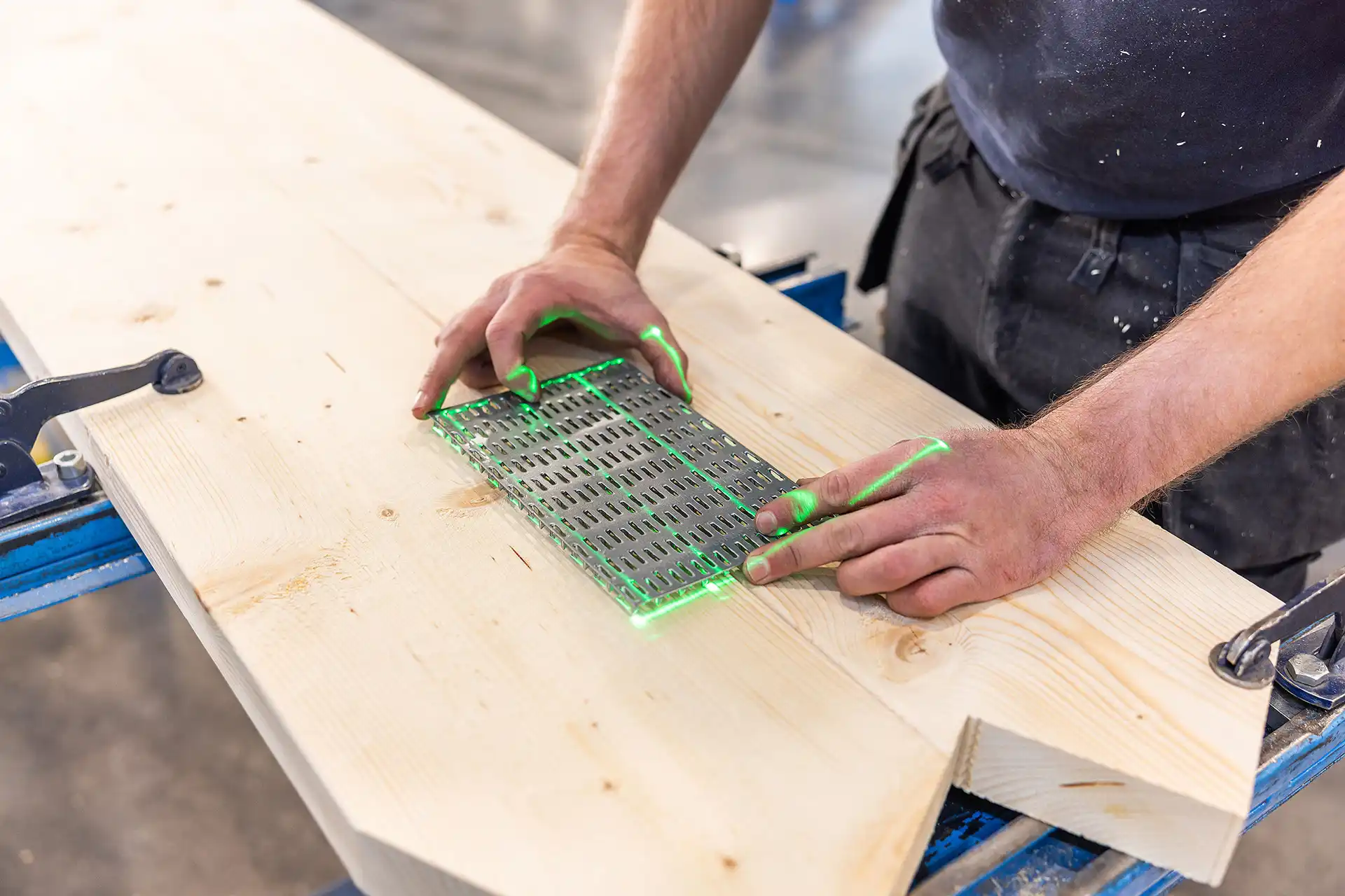
Laser projection supplied by LAP GmbH, integrated into the system, projecting the exact position of each truss member and nail plate onto the fixtures.

LAP CAD-PRO laser projection on the press area

How it works

The fixtures are released, slid into position under each joint of the truss and locked to the steel floor by their magnets. The timber is laid on the fixtures, and supports and fasteners shape it to the correct form while LAP CAD-PRO projects where every member and nail plate goes. With the plates in place, the operator moves the C-press from fixture to fixture, by hand or on a motorised crane, and presses each joint with the two-handed control. The chain hoist lifts the press over the truss to reach the inside joints, and the finished truss is lifted onto a roof truss wagon.

EXAMPLE LAYOUTS

Press lines for the building you have

The press and crane are chosen for your factory: the height and strength of the building, and the nail plates you press. These are example configurations; we plan the exact line with you in a pre-study.

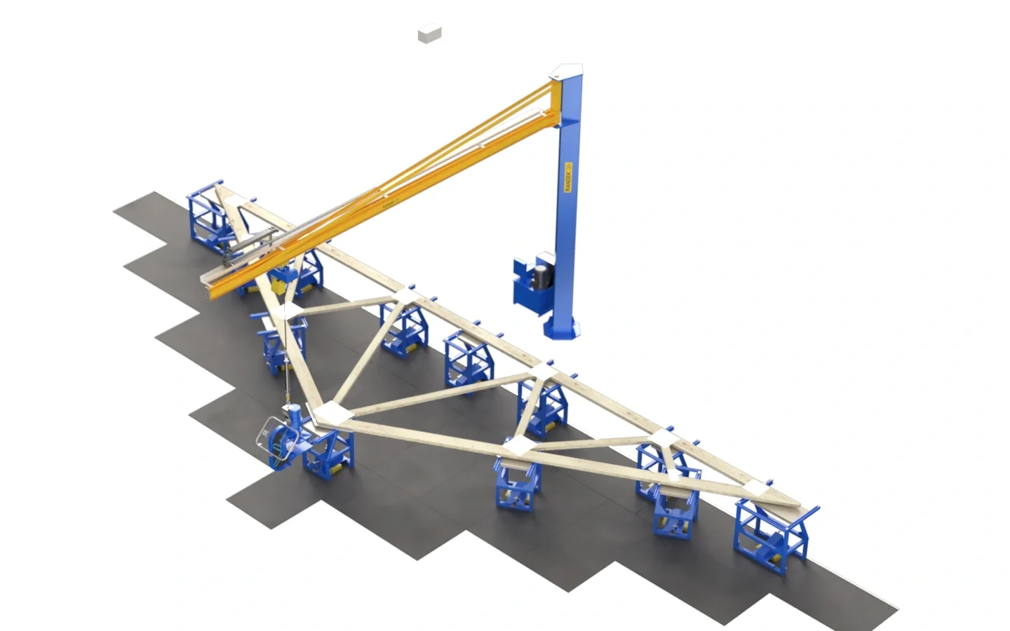
Randek Truss System NT press line with a column-mounted jib crane, magnetic fixtures and LAP laser projection, isometric view
WALL OR COLUMN

Press line with jib crane

A simple and functional press line for all types of trusses. The 7 m crane is bolted to existing wall columns, or to its own column cast into the floor where the walls are too weak or the station should stand free. The operator swings the press from joint to joint.

7 m crane arm, loads up to 320 kg
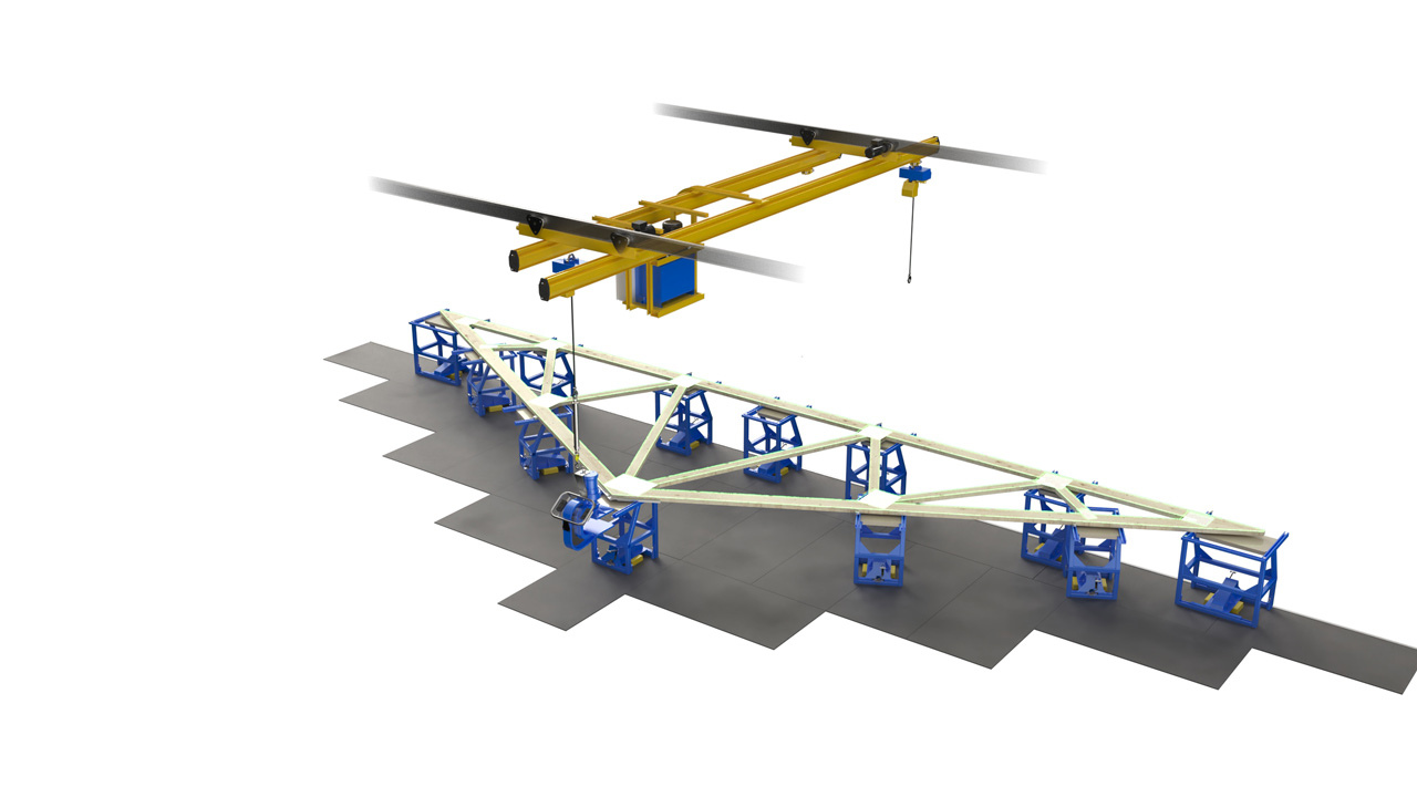
Randek Truss System NT press line with a motorised overhead crane, isometric view
OVERHEAD

Press line with overhead crane

For the heavier 27 and 35 tonne (264 and 343 kN) press heads, a motorised overhead crane runs on a traverse path so the press is never dragged along the truss, and it can serve one or more press stations. The light overhead crane suits 23 to 27 tonne (225–264 kN) heads in buildings with low ceilings; the counter-balanced crane is a motorised alternative directly above the production area.

Motorised for heavy heads, light version for low ceilings
THE NUMBERS

Technical specifications

Press heads23 t27 t30 t35 t50 t
Operation depth315 mm355 mm350 mm390 mm445 mm
Operation height169 mm175 mm153 mm177 mm170 mm
Max nail plate width260 mm400 mm400 mm420 mm460 mm
CranesReachMax loadDrive
Wall-mounted7000 mm arm250–320 kgBy hand
Column-mounted7000 mm arm250–320 kgBy hand
Overhead6 m (or custom)250–320 kgMotorised, frequency-controlled
Light overhead6 m (or custom)250 kgBy hand
Counter-balanced2567 mm range (360°)320 kgMotorised, frequency-controlled
FixturesWidthHeight
NTD 550550 mm832 mm
NTD 900900 mm832 mm
NTP 615615 mm890 mm
Station & utilities 
Typical press stationTen NTD 550 and two NTD 900 fixtures (the wider fixture at the foot of the truss)
Fixture accessoriesRound, truss-top and long supports; quick-grip and eccentric fasteners
Min crane height3700 mm, floor to the lower edge of the crane
Chain hoistElectric, 250–320 kg
Gas spring900 N (23 t), 1400 N (27 t), 1700 N (35 t)
For use with timber and nail plates of roof-truss geometry only. Every Truss System NT setup is configured to the project: the press and crane are chosen for the building and the nail plates used. LAP CAD-PRO laser projection, supplied by LAP GmbH Laser Applikationen, is integrated into Truss System NT and has its own page. The NT10 hand press, for splicing over-long sole and top plates, is a separate product.
SEE IT RUN

Randek Truss System NT in production

How roof trusses are built with Randek Truss System NT and LAP CAD-PRO laser projection
NP Nilsson - Truss System NT med LAP-laser
Downloads

Brochures and flyers

The brochures go into more detail than this page, and they are what you take into an internal meeting.

Your next factory starts here

Talk to Randek

Tell us what you build today and where the bottleneck is. We will point you to the right team: locally where we have one, from Sweden where we do not.

Talk to your team