Products & systems / Floor Jig Tables
Floor Jig Tables
A flexible jig for building floor elements.
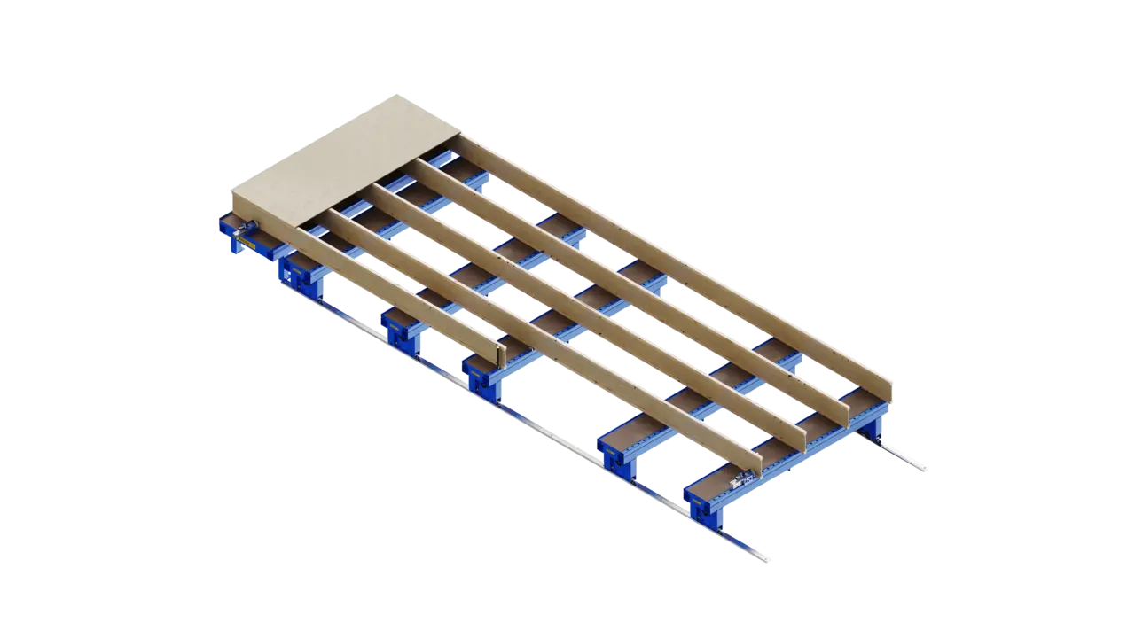
Randek’s Floor Jig Tables are a robust table solution for assembling floor elements: one fixed table that acts as a reference point, plus several movable tables you position exactly where the element needs support. For any builder working in wood, it is an adaptable, low-complexity way to prefabricate floor cassettes accurately by hand.
One fixed table as a square 90° reference, plus movable tables you position exactly where the floor element needs support.
- Support exactly where you need it. Move the movable tables along the floor rails and lock the brake to place support under any part of the element.
- A fixed 90° reference. The fixed table has guiding plates on two perpendicular sides, creating a square corner to build against for repeatable accuracy.
- Positive clamping and alignment. Round supports and cam-lever supports guide and lock studs; pneumatic straightening cylinders clamp and straighten material, including for oblique elements.
- Stays aligned. Movable tables are linked by timing chains so they keep the correct orientation relative to the fixed table.
- Scales to your product. Add movable tables to suit the floor sizes you build.
How it works
Position the movable tables and set the brakes, then place round supports where the element needs them. Lay the floor studs on the jig tables and align them against the supports, clamp with the cam-lever supports, and mount a pneumatic straightening cylinder in the hole beam where needed. The operator then builds the floor element by hand against the fixed reference corner.
Technical specifications
| Capacity | |
|---|---|
| Max element dimensions | 6000 × 3300 mm |
| Max load | 500 kg evenly distributed per table (e.g. ~2000 kg across a four-table configuration) |
| Tables | |
|---|---|
| Fixed jig table | Permanent reference position with guiding plates forming a 90° corner; hole beam (for pneumatic fastening cylinders) and C-bar (for round and cam-lever supports) |
| Movable jig table | Manually movable along floor rails, with raised guiding plate on the fixed side; linked by timing chains for correct orientation; hole beam and C-bar included |
| Pneumatic straightening cylinder | |
|---|---|
| Pressing force at 6 bar | 1870 N |
| Stroke length | 0–200 mm |
| Axis diameter | Ø30 mm |
Talk to Randek
Tell us what you build today and where the bottleneck is. We will point you to the right team: locally where we have one, from Sweden where we do not.